1. Define the problem and required outcome
The process starts with the reason for the repair: repeated blockage, visible fracture, infiltration, root entry, leaking joint or another located defect. The property history and affected fixtures help identify the run, while the intended outcome determines how much inspection and documentation are needed.
The initial scope should separate diagnosis from repair. Restoring flow, cleaning the pipe and installing a structural liner are different tasks. Additional work should be agreed after the condition can be seen rather than treated as automatic whenever a blockage is found.
2. Carry out the pre-lining CCTV survey
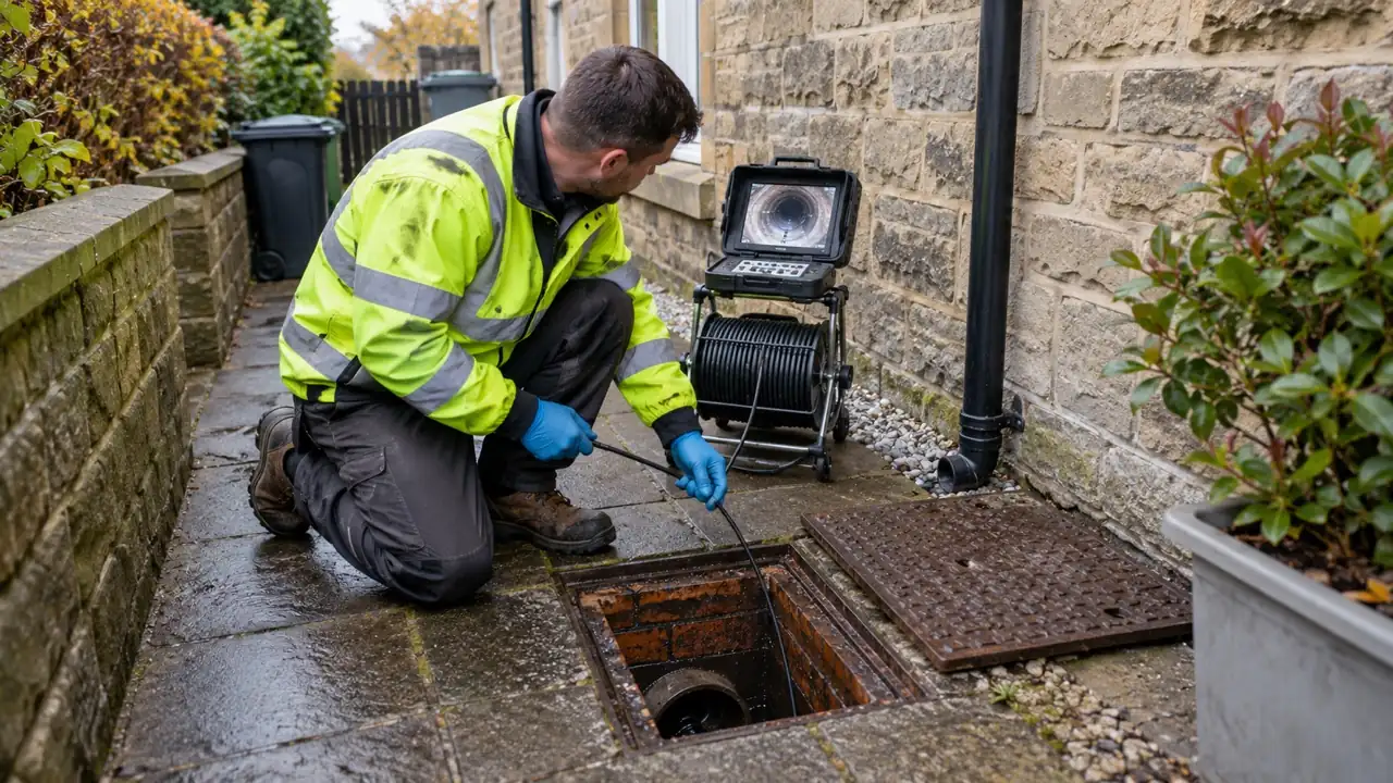
The camera records the access point, direction, pipe material and dimensions where these can be established. Defects, branches, diameter changes, bends and water levels are referenced by distance and, where necessary, surface locating equipment.
If the camera cannot reach the intended section or the wall is obscured, that limitation becomes part of the preparation plan. A design should not assume that an unseen length has the same condition as the visible section.
3. Clear, clean and prepare the host pipe
Restore access
An obstruction may need rodding, jetting or mechanical removal before the whole repair length can be surveyed. The method should avoid forcing equipment through a collapsed or unknown section.
Remove deposits and roots
Grease, scale, silt, roots and loose material are removed to the standard required by the lining system. The pipe wall and junctions must be visible enough to confirm that the liner can sit correctly.
Deal with protrusions
Sharp intrusions, poorly finished connections or severe joint steps can damage or obstruct a liner. Suitable preparation may be possible from within; otherwise a local excavation or different repair may be needed.
4. Complete the design survey and measurements
A second camera pass after cleaning confirms the host pipe condition and final repair length. Measurements cover diameter, liner thickness, end positions, branches and the route through bends or changes. The installer selects a compatible liner, resin and curing method for those conditions.
Resin quantity and working time are calculated for the liner and installation conditions. Temperature affects resin behaviour, so storage, mixing and the expected curing environment must follow the system requirements.
5. Wet out and install the liner
The carrier material is impregnated with the specified resin so it is distributed through the liner. Quality controls should reduce dry areas, trapped air and contamination. The prepared liner is protected until it is installed within its working time.
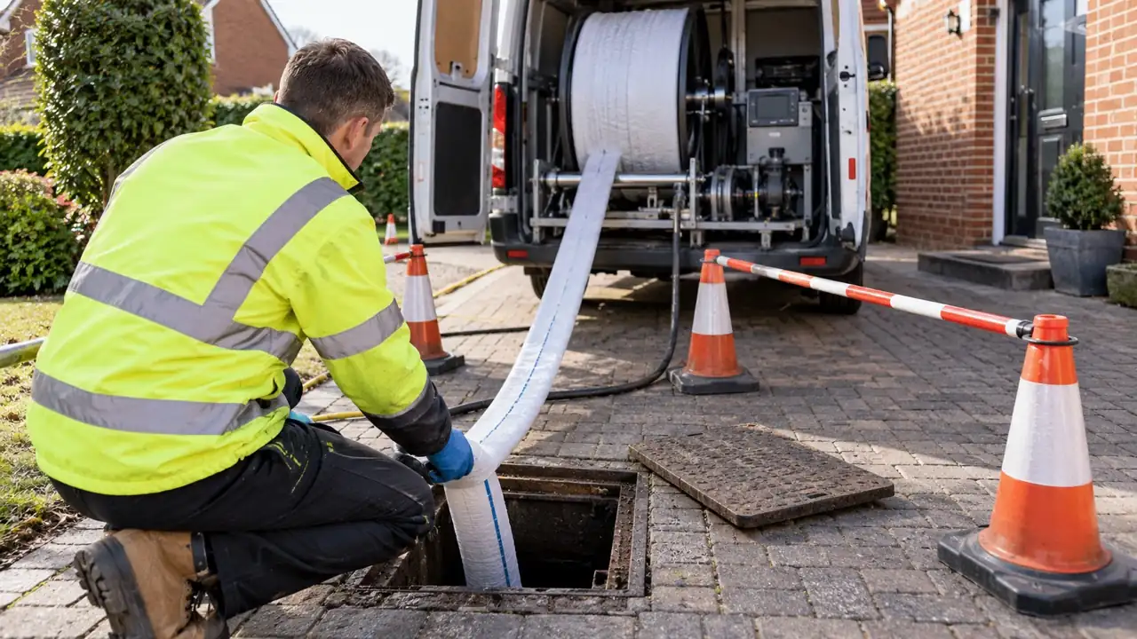
The liner is inverted or winched into the host pipe and positioned across the agreed section. Controlled pressure expands it against the pipe wall. The crew checks end positions and the installation setup before curing begins because changes become much harder after the resin sets.
6. Cure the liner under controlled conditions
The selected system may cure at ambient temperature or use heated water, steam or ultraviolet light. Curing parameters are product- and design-specific. Pressure keeps the liner in shape while time, temperature or UV travel and output are monitored.
The liner must remain stable until the required cure is reached. Removing pressure too early, uncontrolled temperature or an interrupted UV process can affect the finished material. Relevant installation data should be retained with the job record.
7. Trim the ends and reopen connections
After curing, the liner ends are cut and finished at the agreed positions. Any lateral connections covered during installation are reopened using suitable cutting equipment and the survey map. The finish should avoid loose edges or an unnecessary obstruction to flow.
This stage is one reason accurate branch identification matters. A connection that was not recorded before lining can be difficult to locate safely after the host pipe is concealed by the new internal surface.
8. Inspect, test and document the repair
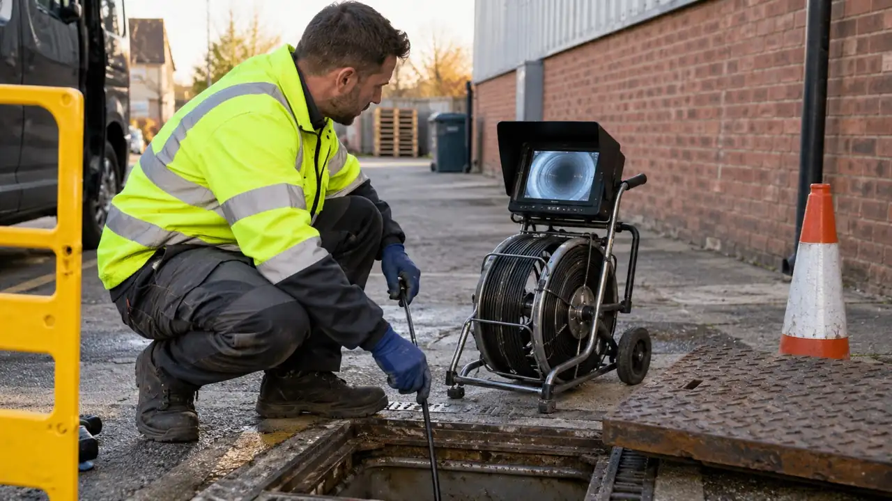
The final inspection is compared with the agreed scope and pre-lining footage. It should show whether the repair is continuous and connections are open, while distinguishing visible confirmation from matters that cannot be assessed by camera alone.
Keep the records with the property. They can prevent a later contractor from mistaking the liner for the original pipe, help select compatible cleaning methods and show where an untreated section begins.
- Post-lining CCTV footage of the complete accessible repair
- The treated length and liner end positions
- Visible finish and reopened lateral connections
- Any section not reached or limitation encountered
- The liner system and curing method used
- Maintenance information and written terms
The process should remain proportionate
Not every defect needs a full-length liner. A local patch, excavation or monitoring plan may be more appropriate, and some jobs use more than one method. The main drain relining page explains the wider repair options and the evidence to request before approval.
BS EN ISO 11296-4 provides standards context for CIPP systems used in underground non-pressure drainage and sewerage renovation. For building work, also consider Approved Document H and any requirements associated with public sewers.
Drain relining in Leeds
This guide provides general information. A repair decision for a particular property needs a survey of the accessible pipe, a located description of the defect and a method suited to the host drain. Review the A1 Drainage Leeds relining page for the service overview and evidence checklist.